GCC linker script and STM32
(a tutorial)

GCC linker script and STM32
(a tutorial)


Introduction
STM32 microcontrollers are organized into families, and every family has its own charachteristics regarding peripherals, memory and flash. This is a fact to be taken into account when compiling and linking your source code. Moreover, every family possess microcontrollers which may have different flash and RAM sizes. All these facts must be taken into account when compiling and linking C/C++ source code.
In this document we want to explain how to modify existing linker scripts, provided by the STM32 firmware library, in order to produce a working firmware for a given STM32 microcontroller.


Multitasking meets C++ in the embedded world > GCC linker script and STM32
The memory layout
The linker script defines the memory layout used by the compiler in order to setup all program sections - code and data.
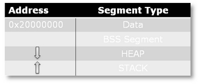
The Cortex-M3 follows a well defined memory (SRAM) layout as shown in the following picture.

‣The Data segment stores the global and static variables initialized by the application code.
‣The BSS segment stores the global and static variable that are not initialized by the application code. The compiler initialize this data to 0.
‣The HEAP is allocated after the BSS segment and it grows in the direction showed in the above picture.
‣The STACK is allocated at the end of the of the SRAM region and is started address is equal to the end address of the SRAM. It the opposite HEAP direction.
Note that a FreeRTOS defines a custom HEAP management schema. The HEAP size id static and defined at compiler time by the configuration macro configTOTAL_HEAP_SIZE located in the FreeRTOSConfig.h file. Usually the FreeRTOS HEAP differs from the HEAP defined in the linker script and it is managed by the couple functions pvPortMalloc and vPortFree.
Linker scripts
Linker scripts are scripts given to the linker in order to specify the memory layout and to initialize the various memory sections used by the firmware when executed. These scripts are essential because they specify the beginning addresses of flash and RAM and also their sizes. Any linker script can be passed to the linker, via G++/GCC (depending on the language used), through the command “-Tscriptname.ld” (see the Makefile associated to this project for an example of a linker commandline including the linker script). Luckily, when we have to modify a linker script in order to compile correctly for a given microcontroller model we must consider only the initial part of it, because this is the crucial part which specifies the memory layout. Following the first part is the code that initializes the various memory sections: this code is boilerplate, so it isn’t necessary to modify it.
Let’s consider now the linker script “stm32_flash.ld” provided by the STM32 library (v.3.2.0 and later) under the folder Project/STM32F10x_StdPeriph_Template/TrueSTUDIO/STM3210C-EVAL Essentially, the initial part is given by these lines of code:
1 /*. Entry Point *./
2 ENTRY( Reset_Handler )
3
4 /.* Highest address of the user mode stack .*/
5 _estack = 0 x20010000; /*. end o f 64K RAM .*/
6
7 /*. Generate a link error if heap and s tack don’t fit int o RAM .*/
8 _Min_Heap_Size = 0; /.* required amount of heap .*/
9 _Min_Stack_Size = 0x200; /*. required amount of stack .*/
10
11 /*. Specify the memory areas .*/
12 MEMORY
13 {
14 FLASH ( rx ) : ORIGIN = 0x08000000 , LENGTH = 256K
15 RAM ( xrw) : ORIGIN = 0x20000000 , LENGTH = 64K
16 MEMORY_B1 ( rx ) : ORIGIN = 0x60000000 , LENGTH = 0K
17 }
Here’s an explanation of the content:
‣The line number 2 (ENTRY) specifies the entry point of the program, that is, the first instruction to be executed in your program. As you can see, ENTRY isn’t referring to the main but to the function Reset_handler present in the startup file. This is normal, because that is the function which initializes the microprocessor and is defined in the startup assembly file (“.s” extension). Usually you don’t have to touch the entry point.
‣The line number 5 declares a variable, _estack, which value represents beginning of the stack. Usually the stack begins at the ending address of the RAM: this has a sense if you consider the growing pattern followed by a stack (from the ending RAM address to the beginning one). You have to modify this value according to the starting address and the size of the RAM present in the SMT32 microcontroller you’re using.
‣The lines number 8 and 9 are self-explanatory and you needn’t to modify them.
‣The ending lines (number 14, 15 and 16) are very important: these specify the memory layout to be used by the program when executed. The most important are the FLASH and RAM memory specifications. For every memory entity specification you must set:
‣read/write/execution privileges (in parenthesis); usually you use the ones pointed out in the snippet above.
‣starting address (ORIGIN value): RAM and flash ones are fixed on every STM32 model, so you don’t have to modify them except in the case you need, for example, to make a custom bootloader and load it in the flash before the main program (but this topic will not be covered in this basic tutorial).
‣size (LENGTH value): this is the value you want to modify and depends on the model you’re using.
‣Every value can be expressed in decimal or in hexadecimal (this depends on your preferences). To be noted that, if you don’t have an external RAM bank, the specification of the memory region MEMORY_B1 can be left out.
These are the basic infos needed to produce a linker script working with your STM32 microcontroller :-)

Copyright © 2011 Stefano Oliveri
All the code is developed for test purpose and it is unsupported. The author assumes no responsibility for any damage caused by improper uses.